Robotics Research 101: How Do Force Sensors Work?

Force sensors are ubiquitous in robotics research (they're everywhere!). But, how do they work? What are the differences between the various types? In this post, we blow apart this core robotics technology and have a look inside. Think of it as a crash course in robotic force sensing technology. It'll get a little bit technical, but we researchers like that, right?
Force sensors detect forces. Simple, you might think. But, is it really that simple? There are actually a huge range of different types of force sensors. We cover several of these technologies in more depth in our new, free eBook Force Sensors in Robotics Research: The Essential Guide (which you can download here). For now, we will look at three important technologies for force torque sensing.
The Basic Option: A Simple Pressure Sensor
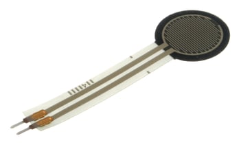
The most basic force sensor is a simple force sensitive resistor. These are mechanical pressure sensors.
As we discussed in a recent blog post, the history of robotic force sensing starts with the development of pressure sensors. Force sensors and pressure sensors are two sides of the same concept, because pressure is force over area. The big difference is that pressure is a scalar quantity while force is a vector. Force sensitive resistors can only detect a single-axis of force applied to one point and in one direction. They are used a lot in hobby robotics for one main reason: they're very cheap.
Force sensitive resistors can be as low as 5 USD and you can even make one yourself using two pieces of wire and some conductive foam. In general, they are not suitable for precision measurements but are good for detecting if a force has been applied or not. The error may be as high as 25%, but if that's good enough for your application then these are certainly an economical option.
The Popular Option: Strain Gauge Force Sensors
A huge proportion of the sensors you'll find in robotics research use strain gauges.
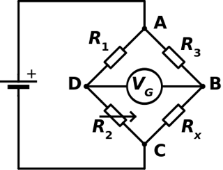 Strain gauges use a simple principle – the resistance of a flexible conductive foil that changes when placed under strain. This resistance change is usually measured using a Wheatstone Bridge, a highly accurate analog circuit, which can be set to produce an analog voltage that is proportional to the resistance change. The voltage is then easily read using electronics.
Strain gauge force sensors generally come in two different forms:
- Single-axis load cells - These are more common in other fields than they are in robotics, such as mechanical engineering and physics. They use a single strain gauge to measure forces in one axis only.
- Multi-axis force sensors - In robotics, by far the most common type are 6-axis force torque sensors. These use multiple strain gauges to detect all forces applied to the sensor in all six axes.
How Strain Gauge 6-Axis Force Torque Sensors Work
As stated above, strain gauges use a simple principle – the resistance of a flexible conductive foil changes when placed under strain.
When used in force sensors, strain gauges are attached to a material with known mechanical properties, like steel. When a force is applied to the material, it will deform elastically. The strain gauge is used to measure how much the material has deformed by detecting its change in resistance. To use this information to find the force, we just use simple materials theory. The calculated deformation is multiplied by the Young's Modulus for a cross sectional area of the material (which are both constants) to calculate the force. Simple, right?
For 6-axis force torque sensors, the principle is exactly the same. Six strain gauges (or often more) are attached to a "cartwheel" of metal bars, with each bar as the spoke of the wheel. Each bar is attached to both the back plate and the front plate of the sensor. Often, there are three metal bars arranged a bit like the Mercedez- Benz logo. At the center sits the electronics, which measure and process the output of the strain gauges.
Are Strain Gauges Really the Best for Robotics?
Unfortunately, strain gauges have several issues which can be a bit of a pain for robotics.
They are quite sensitive to noise because they usually produce an analog signal. Although this effect can be reduced using various techniques, it means that strain gauges are not very suited to high-noise environments. Noise sources can include AC power lines, relays, transformers, motors and arc welders. Robots are often used in factories, which are full of this type of electrical noise.
Other issues include the fact that the strain gauges are attached using an adhesive, which can be a point of failure. They also produce quite a weak signal, which can further increase their sensitivity to noise and requires very accurate sensing circuitry, which is expensive.
However, despite these issues, strain gauge force sensors remain very popular.
The Elegant Option: Capacitive Force-Torque Sensors
Here are Robotiq, we believe that capacitive technology is the next step beyond strain gauge technology. Capacitive force sensors overcome some of the inherent problems with strain gauges and offer a quite elegant way of measuring force. They work on the simple principle that the capacitance of two conductive elements is dependent on the distance between them. An alternating voltage is applied to the elements, which produces an alternating electric current. This current varies depending on the distance of the elements.
As you move the elements together, the capacitance increases. As you pull them apart, the capacitance decreases. This same concept is not only used to measure force, but also to measure liquid pressure, flow and is even used in the touch screens on a mobile phone. Because capacitive sensors use an alternating signal, it means that they are inherently digital. This is a real bonus for robot force sensing because it increases the resistance to noise significantly. Also, it means that we don't have to use an Analog-to-Digital converter, which reduces the required electronics.
But how is this concept used to measure force?
How Capacitive 6-Axis Force-Torque Sensors Work
Just like with the strain gauge Force-Torque Sensors, the two ends of the sensor are attached through a compliant metal element. However, this time it is not in the form of a "metal cartwheel." Instead, in our capacitive sensors at least, this element consists of an intricately machined metal block which is designed to deform in a particular way under force. This structure is attached to two metal plates (one at each end). These plates hold a specially positioned set of capacitive sensors to measure the displacement between them.
There are several advantages to using capacitive sensors in FT Sensors over the traditional strain gauges, in addition to their immunity to noise. Capacitive sensors generally produce a stronger output so less signal conditioning is needed, which ultimately means better accuracy. Also, capacitive sensors don't rely on the adhesive bond between the metal and the strain gauge, meaning that they can withstand millions more force readings without affecting their accuracy.
Understanding the Electronics
The integrated electronics of a Force-Torque Sensor allow you to easily access the data. Most of the Force-Torque Sensors we use in robotics have integrated electronics, which thankfully means you don't have to do the signal processing yourself. They also have a variety of different communication options which allow you to easily get the data from the sensor.
The integrated electronics convert the multiple sensor readings into six easy to understand signals: Fx, Fy and Fz (the forces) and Mx, My and Mz (the Torques or Moments).
Mathematically, this conversion is often carried out by multiplying the sensor readings with a pre-defined matrix. The matrix is defined by the sensor's manufacturer and are dependent on the material properties of the compliant metal structure. These properties will never change, unless you plastically deform the metal by applying too much force to the sensor.
As you can imagine, it's important to make sure you never apply too much force to the sensor, as the whole of its operation is based around the fact that the metal should never deform plastically. That's why you should pay attention to the Maximum Overload Capacity when choosing a Force-Torque Sensor for research.
Choosing (and Using) Force Sensors in Your Research
However, Maximum Overload Capacity is not the only important specification when choosing a force sensor for your robotics research. There are a whole load of specifications which affect which choice is the best for your application. Once you've decided these specifications, you've got to decide how to apply the sensor to your research and what are the best ways to integrate it into your existing system.
Wouldn't it be great if you had one place you could find all this information? We've developed a free eBook and email series to give you a crash course in using force sensors for robotics research. In it, we cover more detail about how they work, guides to integrating force sensors into your research application, how to use ROS with a force sensor and much more.
Download the eBook by clicking the big button below! (Did we mention, it's free!)
How do you, or how would you like to, use force sensors in your research? Have you downloaded the free eBook? Do you have any questions about force sensors? Tell us in the comments below or join the discussion on LinkedIn, Twitter or Facebook.





Leave a comment