How Does a Parallel Robot Gripper Work?

Posted on Feb 24, 2015 in Robot Grippers
5 min read time
Choosing a robot gripper can sometimes be confusing. As there are a wide choice of different grippers out there, you really want to make the right choice for your applications. Some gripper manufacturers will be promoting the performance or reliability of their grippers without even considering your needs. This article will discuss only one type of industrial robot end effector: the parallel gripper.
The etymology of the phrase, parallel gripper, relates to the fact that the gripper's fingers will remain in perfect parallelism throughout all the gripper's opening and closing movements. A parallel gripper is generally used for pick and place operations where parts have a predictable geometry. In other words, the gripper will be specific to a given geometry. This means that the gripper will close around the object and hold it during whatever motions the robot arm is making and will release the object afterward. There are two general categories of parallel grippers: pneumatic parallel gripper and electric parallel grippers. As there are a lot of variations in the design of the grippers depending on the company, I will try to explain the general or most popular functionalities of parallel grippers.
Pneumatic Gripper
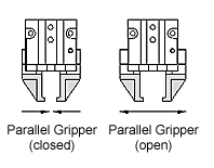
Pneumatic grippers, as the name proposes, works with compressed air. The gripper is connected to a compressed air supply network. When air pressure is applied on the pistons, the gripper closes. When the pressure is released the gripper opens. The only way to manage the force in the gripper is to manage the air pressure in the air intake (or valve).
To further elaborate on this concept, imagine that the gripper is two pneumatic actuators placed in opposite directions. Referring to the figure below. When the robot program asks the gripper to close against the part, first the valve (colored in green) is moving right to let the air pressure enter into the left portion of the pneumatic actuator (colored in pink). As the pressure builds up in this section, the piston moves in the ''x'' direction. The piston will then apply a force according to the pressure on the piston (Force = Pressure * Surface). To keep a constant force on the part, the valve can be closed or remains open and must keep a constant air pressure on the piston.
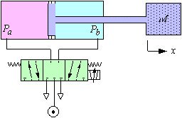
When the program requests the release of the part, the valve then moves left and the air pressure goes into the right section of the cylinder (colored in blue), at the same time the air in the left section is released. This operation brings the piston back to its initial position. This way, the part is also released.
As both actuators are attached to each individual finger in direct opposition to each other, the piston controlling the fingers will close against each other in perfect synchronization. This example is a simple representation of how it works, however, a lot of different design exist. The disadvantage of using this kind of gripper is that there are very few settings that can be controlled on the fly. In fact, the stroke is fixed for a given gripper and the force has to be adjusted with the pressure that flows into the valve. It takes a couple of tests to figure out the amount of air pressure that will work well for each particular application. It also takes custom fingertips for every different object that has to be grasped.
Notice that the working principle for a pneumatic gripper can be compared to a hydraulic gripper. In this case, the fluid is oil or water instead of air. Other types of pneumatic gripper exist on the market, check this past blog post for more information.
Electric Gripper
Electric grippers are actuated by electric motors. A lot of different motors can be used in this type of gripper (servo, steppers, etc.). Most of the time, the principle is a 4-bar linkage that translates the motions of the motor rotation into linear motion.
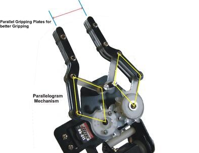
There are different ways to synchronize the fingers. In some cases, a single screw will turn and a mechanism will go up and down as the fingers open and close. Other designs use gears (as shown in the figure) to make sure the two fingers open and close together.
The 4-bar linkage or parallelogram mechanism is quite complex to understand. But the baseline is that, since all the bars have a fixed length, opposite bars will always remain parallel. Most of the time, there is one actuated pivot and all others pivots are free to turn around their end. Most designs for electric grippers will have gear nubs that stop the finger motions. These nub stops will mark the longest stroke the gripper can reach.
The advantage of using an electric gripper is that it is possible to adjust the finger stroke with simplified programming methods. Some models even allow you to adjust force and speed. These grippers normally can also be customized to have various fingertip shapes which would allow a wide range of objects to be grasped.
With all parallel gripper models, there is no way to encompass the object that you want to grab. This is a serious downside when it's time to automate a process with circular parts or even with irregular parts. Since only two point of contacs are established on the part instead of four in the encompassing mode. To have a robot end effector that is capable of making an encompassing gesture, you need to go with an Adaptive Gripper. These grippers are electric grippers with a 5-bar linkage that allow encompassing motions. They can also be adapted really quickly to do parallel grasping.
To get more information on how to select your future robot end effector, take a look at the link below. In the mean time, subscribe to our blog to get weekly blog posts on robotic news and technologies.

.jpg)


Leave a comment