![logo bleu-blanc2.png]](https://blog.robotiq.com/hs-fs/hubfs/logo%20bleu-blanc2.png?height=40&name=logo%20bleu-blanc2.png)
The palletizing collision model tells the robot what it must avoid when it plans a trajectory. Registering a bounding box adds a volume to that model, and the robot then treats it as an obstacle and plans around it. This article covers the rq_register_bounding_box() script function: its parameters, the referentials it accepts, and how the box position and dimensions are expressed.
Note: Adding safety walls, pallet walls or a conveyor to the model should be achieved using other existing methods. It is also possible to change the default gripper representation with a custom design gripper using the guide available here: 3D Model for the Gripper Mesh File.
Recommendation: read these three articles in order.
- Plan the bounding box you will add: How to Create Bounding Boxes with the Online Configurator
- Use the present article to understand how the script function works.
- Consult the resulting model: How to consult Collision model for Palletizing Solution
Function to create a collision box
rq_register_bounding_box() (Public and supported)
Description
This script is used to place a bounding box of a specific size, at a certain position according to a referential in the virtual environment of the robot. The robot will consider the bounding box an obstacle and plan its trajectories accordingly.
Declaration
rq_register_bounding_box(referential, position, dimensions)
Parameters
| referential | (type: integer) |
| Referential to be used for the bounding box. The most common are 0, 3 and 9. | |
| 0 = palletizer base | |
| - AX: like #1 but at the lowest position of the axis, turn 180° from #3 | |
| - PE : on the ground under the robot base, turn 180° from #3 |
|
| 1= linear axis column / pedestal lower part | |
| 2 = linear axis chariot/ pedestal upper part | |
| 3 = RobotBase | |
| 4 = RobotBaseShoulder | |
| 5 = RobotShoulderElbow | |
| 6 = RobotElbowWrist1 | |
| 7 = RobotWrist1Wrist2 | |
| 8 = RobotWrist2Wrist3 | |
| 9 = RobotFlange | |
| position | (type: pose) (unit: meter / RAD) |
Format p[X,Y,Z,Rx,Ry,Rz] |
|
| The origin of the box is in the center of the face that is opposite to the direction of Z of the reference. | |
| For a reference in 0 or 3, it is on the bottom of the box. For a reference in 9, it’s on the top of the box. | |
| Rotations are around the chosen referential’s axis and in axis-angle (not euler). | |
| For multiple rotations, the rotation around X axis will be applied first, then around Y and finally around Z. | |
| dimensions | (type: list) (unit: meter) |
Format [x,y,z] |
|
| The dimensions of the box dimension in length, width and height according to the referential. | |
| For referential 9, that would be the tool flange. |
Return value
No value is returned.
Example
rq_register_bounding_box(0, p[0.52, -0.123, 0.427, 0, 0, 0], [1.4, 0.6, 2.7])
See Collision consultation to validate the position and size of your box in the robot's virtual environment. This should only be used in the application's debugging stage. Once the program is functional, it should be removed.
Precisions on Referentials
Referential (type: int)
Three useful referentials are:
0 = palletizer base (AX series)
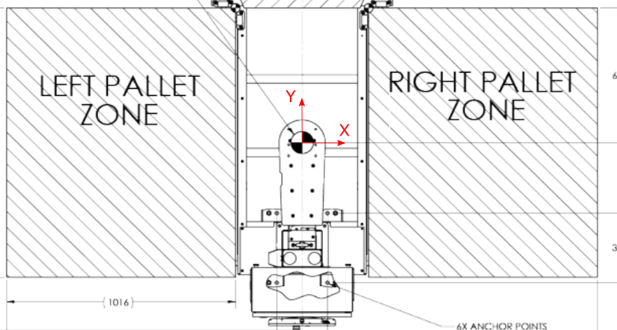
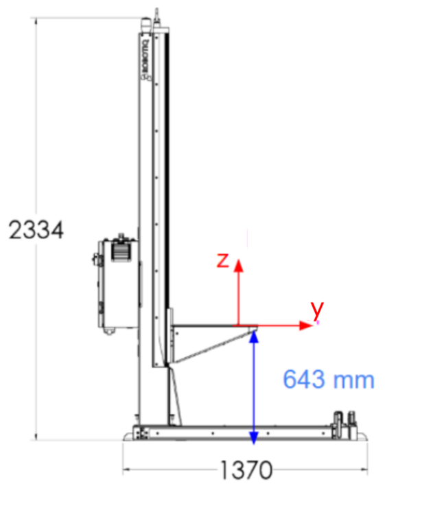
3 = robot base 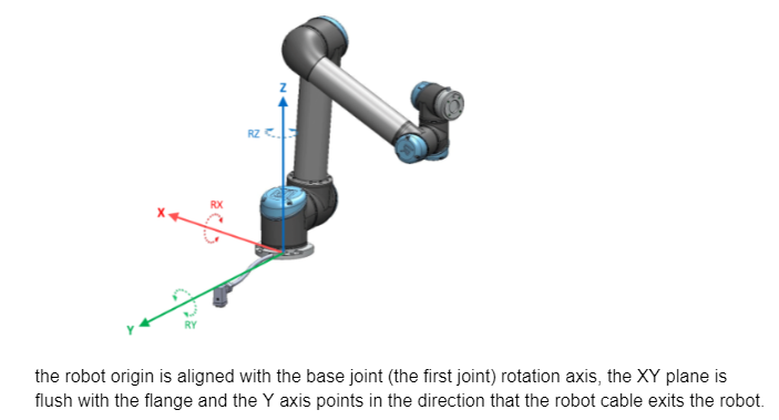
9 = robot tool flange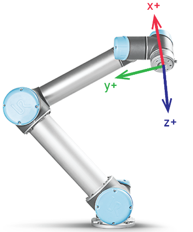
Box position (type : pose)
The box position is written in the p[X,Y,Z,Rx,Ry,Rz] form. The box origin is the center of the bottom of the box. Of course, what is the bottom and the top is relative to the referential frame.
- X, Y and Z are in meters.
- Rx, Ry and Rz, in radians.
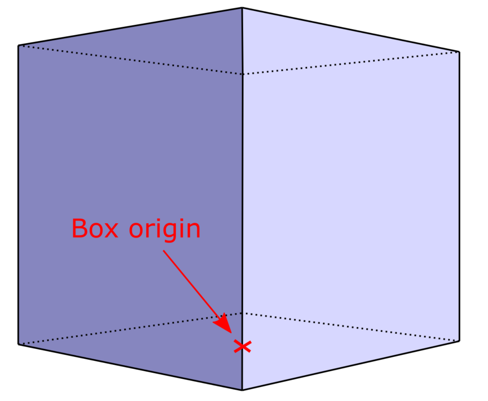
Box dimensions (type : list)
Box dimensions are presented in the [X,Y,Z] form and must be expressed in accordance to the selected reference frame.
X, Y and Z are expressed in meters.
Example with boxes added in the tool reference frame
Here we need to avoid collisions with a custom tool with an irregular shape.
Here is a view of the resulting collision model, which includes the auto-generated boxes of the extension bracket and the gripper (this one is on top, aligned with the gripped box, and slightly smaller). 
Conclusion
A bounding box is the simplest way to make the palletizer aware of an obstacle that is not part of its standard model. Plan the box first, register it with rq_register_bounding_box(), then validate its position and size in the robot's virtual environment before removing the consultation code from the production program.
Need help? Contact Robotiq Support.
Updated: August 26, 2026