Context
By default, Robotiq’s palletizer software uses a simplified box to represent the gripper in its collision model.
Our recommendation is to stay with automatic gripper modelisation or to use the feature "define custom gripper model here :

However, for specific cases it can be usefull to modelise accuratly the gripper.
This article explains how to replace that placeholder with a real 3D mesh model.
Note : A simpler model results in faster calculation times.
Information
1. Get the Mesh Model of the Gripper
-
If you're using PowerPick, you can use existing models from the PLY Models folder.
-
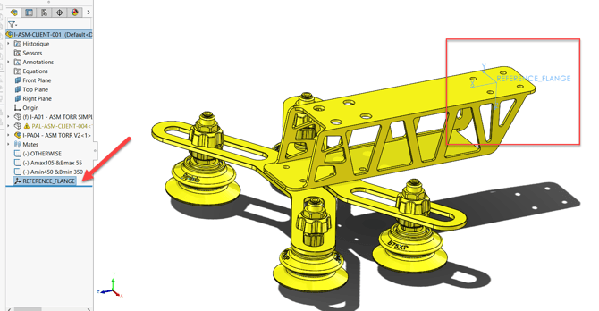
Otherwise, open your gripper’s CAD assembly in a 3D modeling software like SolidWorks.
2. Create a Reference Coordinate System
You have two options depending on your needs:
-
Flange-Based (Recommended for fixed geometry):
-
Align the coordinate system with the robot's flange.
-
X-axis should point toward the pick direction.
-
Z-axis should point away from the flange
-
-
TCP-Based (For multiple gripper offsets):
-
Place the coordinate system at the TCP (e.g., center of the box's top face).
-
3. Export to STL Format
When exporting the model from your CAD software:
-
File format:
.stl -
Open the Options before saving and set:
-
Units: meters
-
Resolution: coarse
-
Output coordinate system: use the one aligned to flange or TCP
-
🧠 Tip: Aim for 1000–2000 triangles to keep cycle time optimal. Use simple geometric shapes to reduce mesh complexity.

4. Convert to .PLY Using Meshlab
-
Open your
.stlfile in Meshlab (free tool). -
Export the file as a
.ply.
🛠 To reduce triangle count in Meshlab:
Filters > Remeshing, Simplification, and Reconstruction >
Simplification: Quadric Edge Collapse Decimation
5. Upload the Mesh File to the Robot
-
Use an FTP tool like FileZilla
-
Transfer the
.plyfile to the robot’s/programsfolder
6. Load the Mesh in the Program
Ensure you’re using Copilot URCap V1.29.0 or higher
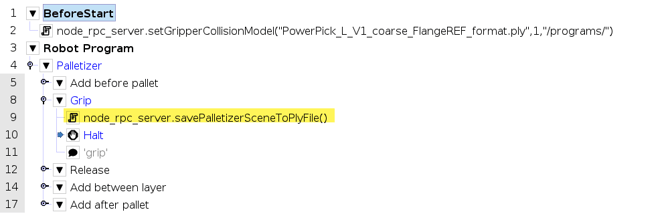
In the Before Start section of your program, add:
rq_set_gripper_collision_model("FileName.ply", 0)
Or specify the file path if needed:
rq_set_gripper_collision_model("FileName.ply", 1, "/programs/meshes/")
Parameters :

7. Verify the Collision Model
To debug or validate, use the following command (for setup only — remove in production):
node_rpc_server.savePalletizerSceneToPlyFile()
This saves a .ply file of the full collision scene (after running at least one trajectory).
-
File location:
/root/robotiq/logs/ucs/rq_xmlrpcserver/palletizer_collision_scene.ply
example :
You will generate a file of the collision scene, that you can then view with Meshlab.
Note : You need to run at least one trajectory for the model to update itself with the request.
Open this in Meshlab to confirm the mesh is active. Here before /after :


8. Revert to the Original Model
To switch back to the default box model:
-
Remove the
rq_set_gripper_collision_model()script line -
Restart the robot
Conclusion
Adding a 3D mesh improves the accuracy of your palletizing simulation. Be sure to reduce mesh complexity to maintain cycle performance and validate your model using the debug command.
Contact Robotiq Support if you need help with mesh formatting.