

Since there are little to no established standards for attachment interfaces in the robot industry, many things are to be considered by end-effector manufacturers, integrators and users for end-effector attachment design. This post first explains how to determine the forces and moments that your end-effector attachment must hold. Then, we present ways of attaching the end-effector to the robot. An Excel spreadsheet can also be downloaded to get you started in your calculations.
How to design the interface
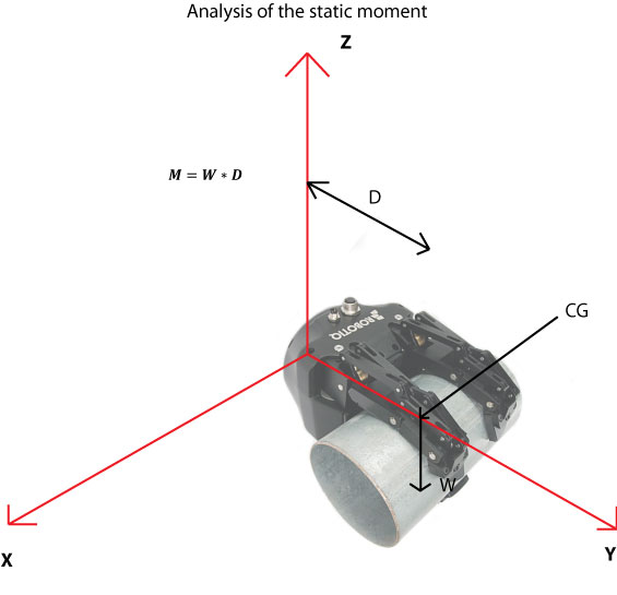
Basic method: the static moment.
- Find the center of gravity of the end-effector and the part: CG
- Calculate the distance from the CG to the bottom of the tool plate: D
- Determine the maximum weight of the EOAT and the part: W
- Calculate the static moment
- Select your interface so it can hold the the maximum static moment - note that the interface height adds to the distance D and increases the moment M
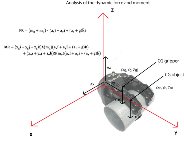
Advanced method: dynamic forces and moment analysis.
- Determine the CG of the object and of the gripper
- Determine the maximum weight of objects that will be grasped and of the gripper
- Determine the maximum acceleration occurring during the process
- Calculate the resultant force
- Calculate the resultant moment
- Select your interface so it can hold the the maximum static moment - note that the interface height adds to the distance D and increases the moment M
How to attach the interface
Now that you know the maximum payload and moment you can handle, you have to attach your end-effector to the robot. Keep in mind the height of the interface stacks to the centroid distance D. Increasing D does increase the resulting moment.
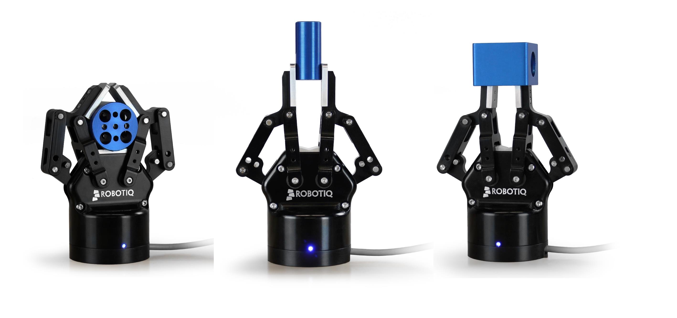
Using a faceplate: Related to the robot model, you will have various screw and dowel pin patterns.
- Screw the faceplate on the robot
- Insert the gripper, dowel pins provide orientation, precision and repeatability (each time you remove the gripper for tool changing or maintenance, the dowel pin ensures repeatability)
- Secure the gripper with the screws matching the interface, using Loctite will help
The above methods can also be used to determine the required specification for a robotic tool changer. On this topic, you can read the top 5 problems of robotic tool changers.


Leave a comment