When starting the PAL-AX10 v1.3 linear axis, you may encounter the error message:
Please use the safeguard reset before starting the linear axis
This error occurs because the system requires a safeguard reset before the axis can be initialized. This safety step ensures the robot environment is secure before movement.
If the Error Persists
If you have already double-checked the Safeguard Reset wiring and Safety I/O configurations but still cannot clear the error:
-
The safeguard reset is primarily handled by the wiring inside the UR controller.
-
However, a second validation check is performed by the Siemens PLC.
-
If there is a mismatch between:
-
The URCap check (Festo Drive)
-
The Siemens PLC check, the safeguard reset error will remain active.
-
In other words: even if the wiring is correct, a disagreement between the UR and PLC validation may prevent the error from clearing.
Troubleshooting Steps
-
Check Siemens PLC LEDs
-
Press the pallet sensors:
-
Left sensors → DI0 & DI1 should light up.
-
Right sensors → DI2 & DI3 should light up.
-
-
If these LEDs light up, proceed to the next step.
-
If they do not light up, check PLC power and confirm the RUN light is green.
-
-
Check the Safety Status LED (DI4b)
-
Locate the Safety Status LED on the Siemens PLC.
-
DI4b must be ON.
-
If the LED is OFF, there is a wiring issue with the safety status check.
-

Solution: Check the 24V Line with a Voltmeter
If the above checks fail, confirm the 24V wiring between the Safety Relay and the Siemens PLC:
-
Probe the Siemens Safety Relay at Port 2, Wire 55.
-
You should measure 24V.
-
(Probing in continuity mode also works.)
-
-
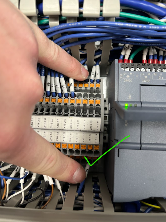
Probe the PLC terminal X16, pin 1.13 (Wires 55/60).
-
You should still measure 24V.
-
(Probing in continuity mode also works.)
-
If 24V is not present at one of these points, the issue is in the wiring between the Safety Relay and the Siemens PLC.
-
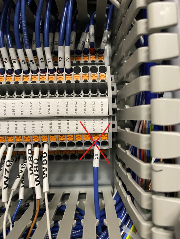
Finally, probe between Wire 60 on terminal X16 1.13 and DI4b on the Siemens PLC.
-
At this point, you may discover that one of the wires is not connected to the correct terminal.
-
Ensure all wires are securely fastened into the correct ports and terminals.
-
Need help? Contact Robotiq Support