roubleshooting
1. Check Each Connection in the Circuit
Screw Feeder
-
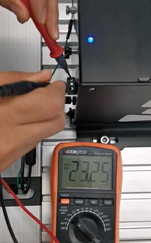
Use a multimeter to verify that 24 V is present on both output pins at the back of the feeder.
-
To measure voltage:
-
Place one probe on either READY or STATUS pin.
-
Place the other probe on GND.
-
If you don’t measure 24 V, there may be an internal wiring issue inside the screw feeder.
Controller
-
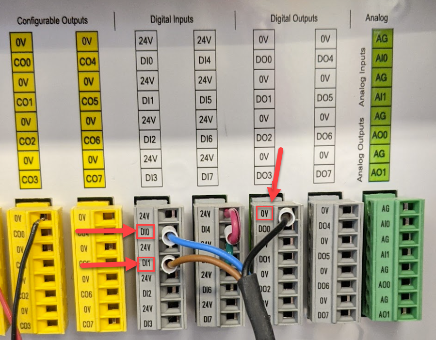
Check that the wires connecting the screw feeder to the robot controller are:
-
Properly screwed in
-
Connected to the correct input slots
-
-
If any wires are loose or misaligned, reposition and secure them firmly to ensure proper signal transmission.
Robot Installation
-
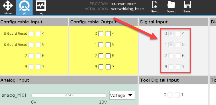
Open the I/O tab on the robot interface.
-
Observe the Digital Inputs while:
-
Turning the screw feeder ON and OFF
-
Detecting a screw
-
Manual Test
-
To manually test an input:
-
Use a small wire to connect a 24 V slot to the Digital Input (DI) slot you want to verify.
-
This simulates a signal and helps confirm if the robot is receiving it.
-
-
If the input still does not respond, try a different DI slot on the controller.
URCap
-
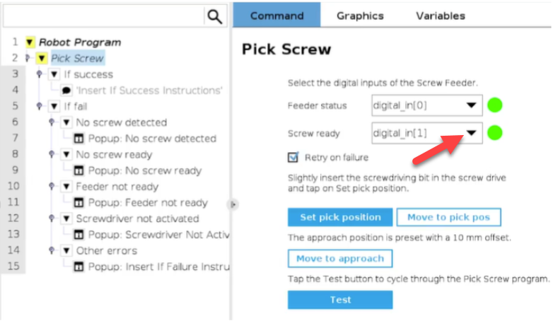
In your program, open the Pick_Screw node.
-
Verify that the correct Digital Input is selected from the drop-down menu.
-
If needed, test other available inputs to determine which one corresponds to the signal from the screw feeder.
PNP / NPN Configuration
-
Ensure the system is set to the correct PNP or NPN mode, depending on your wiring.
In PNP mode (reverse logic for NPN):
-
IO Screw Ready:
→ 24 V when a screw is ready
→ 0 V otherwise -
IO Status:
→ 24 V when the feeder is running properly
→ 0 V if there is a fault
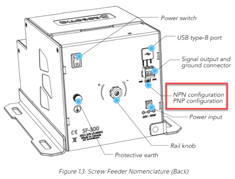
Info:
For Universal Robots, the switch should be toggled to PNP (towards the rail knob).